The communications server provides the interface between 'LocoNet' and the control system applications.
I have a 'Track' Loconet and a 'Signalling' loconet.
The Track loconet has:
1. Power Management (PM42/PM74)
2. Train Detection (BDL162/BDL168)
3. Point Controller (DS64)
4. Wireless Interface (IoTT)
5. Throttle Connections(UT3's,UT5's)
6. Control System Interface (PR4)
The Signalling loconet has:
1. LocoIO Interfaces (Digital inputs/Ouputs)
2. LocoServo Interfaces (Servos)
3. Control System Interface (PR3)
('LocoNet' is the "Digitrax" communications protocol which allows accessories to talk to each other and the command station)
The Interlocking is the heart of the system, and provides for the operation of the points and signals in a prototypical manner.
The layout is sectionalised to provide prototypical track circuit sections using mainly "Digitrax" BDL162/DDL168 modules which give 16 track sections, I have 9 of these so 144 track sections.
Recently I have added some 'MGP' detectors, which are connected to an IoTT
"Yellow Hat". These work really well and are cost effective.
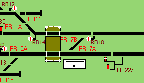
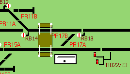
Route setting uses BR style NX, clicking the mouse on the eNtrance signal, then the eXit signal, if the route is available the required points are called, and when all in requested position the signal clears to proceed (Yellow), if the next signal is at proceed then the aspect is upped to Green.
The line of the route is shown in 'white' with the positions of the points.
Route availability is calculated by algorithms for each route.
The Timetable application allows for trains to be run automatically to predefine 'paths' at set times after the timetable starts.
Trains stop at stations, wait in passing loops and play sound effects like whistles when approaching tunnels etc.
Additionally, trains can also be manually driven on a path outside of the timetable.
The track is a mixture of 'Peco' code 100 in the non scenic areas and 'SMP' code 75 in the scenic areas.
Recent repairs have used 'Peco' Bullhead rail which is compatible with 'SMP'.
'Peco' points are used in the non-scenic areas, and hand built points using copper clad sleepers in the scenic areas.
Point operation is by either, solenoid, slow motion motors or servo motors.
I am in the process of converting all point operations to servos.
All points have live frogs and position detected using attached micro switches and relays as required.
Both colour light and semaphore signals are used on the layout.
The main station 'Robstown' has working colour light signals including route indicators, call-on and ground signals.
The signals controlling the entrance to the 'Fiddle Yard' have working 'Theatre' lights showing 1 to 9.
The branch line stations and 'Robford' has servo driven working upper quadrant semaphore signals, the ground signals are currently static.
I have added 'micro' led's to some Semaphore signals to light the 'spectacle'
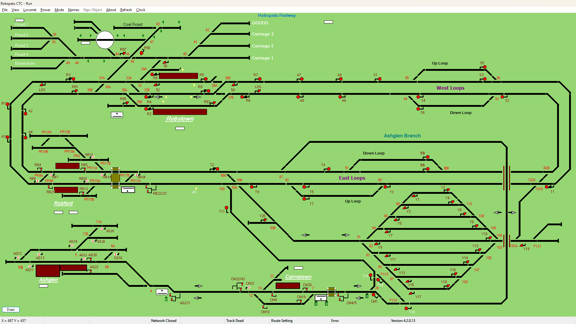
This is my layout, whilst it looks to be a complete oval, it is in fact a folded figure of eight, with a branch line.
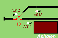
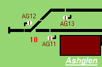
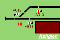
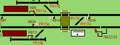
Route setting is preformed using the prototypical NX(eNtrance/eXit) method by clicking the mouse on the required signal icons.
Semaphore signals require just a single click
As per prototype control systems, track circuit occupancy is shown in red route, route set is shown in white. 4 Digit train descriptions are shown in green.
First Digit = Train Class
Second Letter = Route
Third/Forth Digit = Loco Address.
Additionally I have added the loco name, which is not prototypical, that moves with the train description.
Landing Page Software